Logic gates (CMOS)
7.1 · The CMOS inverter (NOT) — 2 transistors
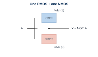
Section titled “7.1 · The CMOS inverter (NOT) — 2 transistors”Wire a few transistors together and you get a logic gate, a circuit that computes true/false, where a 1 is a high voltage and a 0 is a low voltage. The simplest is the CMOS inverter (NOT): one PMOS above one NMOS. When the input A is 1 the NMOS pulls the output low; when A is 0 the PMOS pulls it high. In any steady state one side is off, so the gate burns almost no power — the reason CMOS won.
7.2 · The gate toolkit & transistor counts
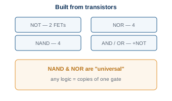
Section titled “7.2 · The gate toolkit & transistor counts”From the inverter and a handful more transistors you get the whole toolkit: NOT from 2 transistors, NAND and NOR from 4 each, and AND/OR by adding an inverter. Remarkably, NAND and NOR are universal — any logic function at all can be built from copies of just one of them, so the entire logical universe of a computer reduces to one repeated pattern.
7.3 · Truth table — the numbers behind the logic
Section titled “7.3 · Truth table — the numbers behind the logic”Each gate is completely defined by its truth table, which simply lists the output for every combination of inputs. Read across the rows and you can see exactly how AND, OR, and XOR differ. This is the level where we stop thinking about electrons and start thinking purely in 1s and 0s.